Imagine you have just finalized the perfect CAD model for a revolutionary new product, but when you send it for prototyping, the manufacturer rejects it immediately due to “undraftable features.” You face weeks of redesigning, skyrocketing development costs, and the sinking realization that your launch date is slipping away because the design cannot be ejected from a tool. This common nightmare scenario plagues countless designers who treat manufacturing as an afterthought rather than a foundational constraint. By mastering the fundamentals of the plastic injecting mould process—from draft angles to wall thickness—you can eliminate these expensive delays and ensure your product scales seamlessly from prototype to mass production.
Introduction
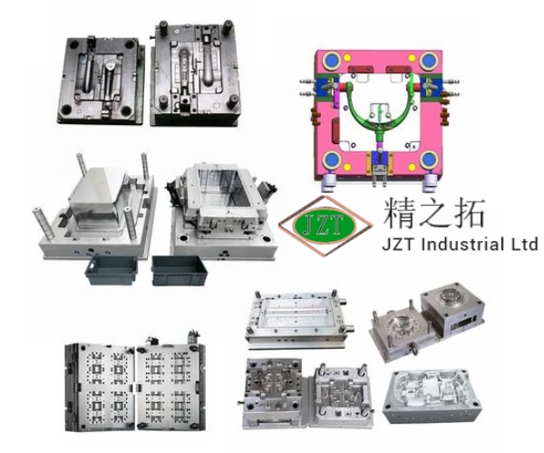
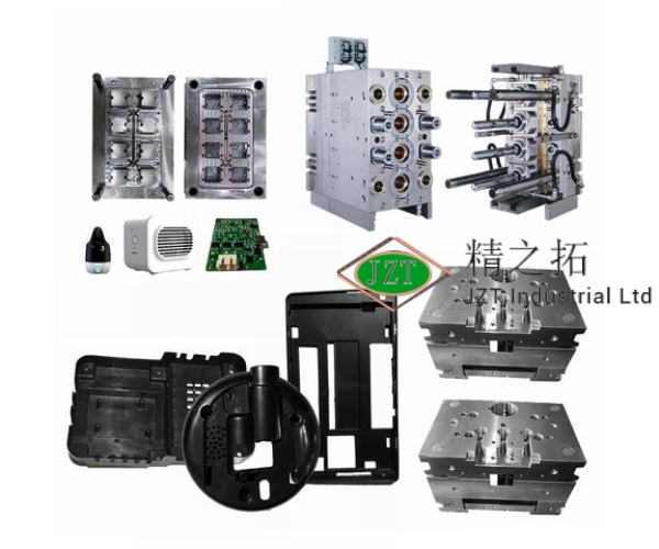
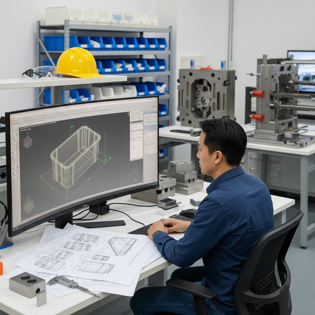
Injection molding is the premier manufacturing process for producing high-volume plastic parts with exceptional repeatability and minimal material waste. It transforms raw plastic pellets into precise components by forcing molten material into a custom-machined metal tool under high pressure. To achieve this, you must invest in high-quality custom plastic injection molds that serve as the negative of your final part, dictating everything from surface finish to structural integrity. This guide explores the critical design, material, and processing decisions you must make to leverage this technology effectively.
How Does the Plastic Injecting Mould Process Work?
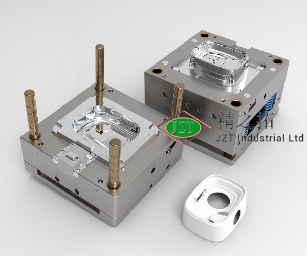
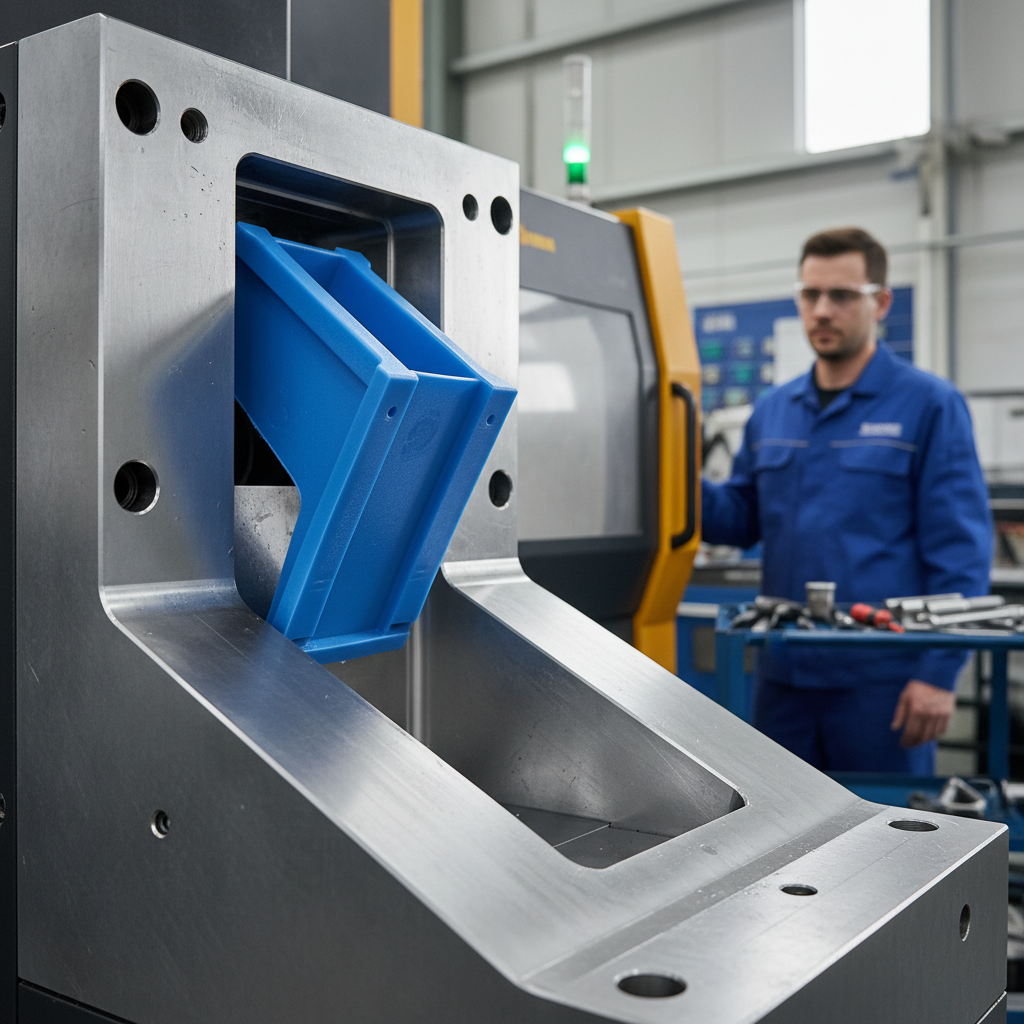
The process functions by injecting molten thermoplastic resin into a robust metal tool, where it cools and solidifies into the final component shape. A plastic injecting mould is typically CNC machined from aluminum or hardened steel to withstand the immense pressures of the injection phase, often exceeding thousands of PSI.
Once the mold is clamped shut, the machine’s screw auger melts plastic pellets and injects the material into the mold cavity. The part is held under pressure until it is rigid enough to be ejected, at which point the cycle repeats immediately for the next unit.
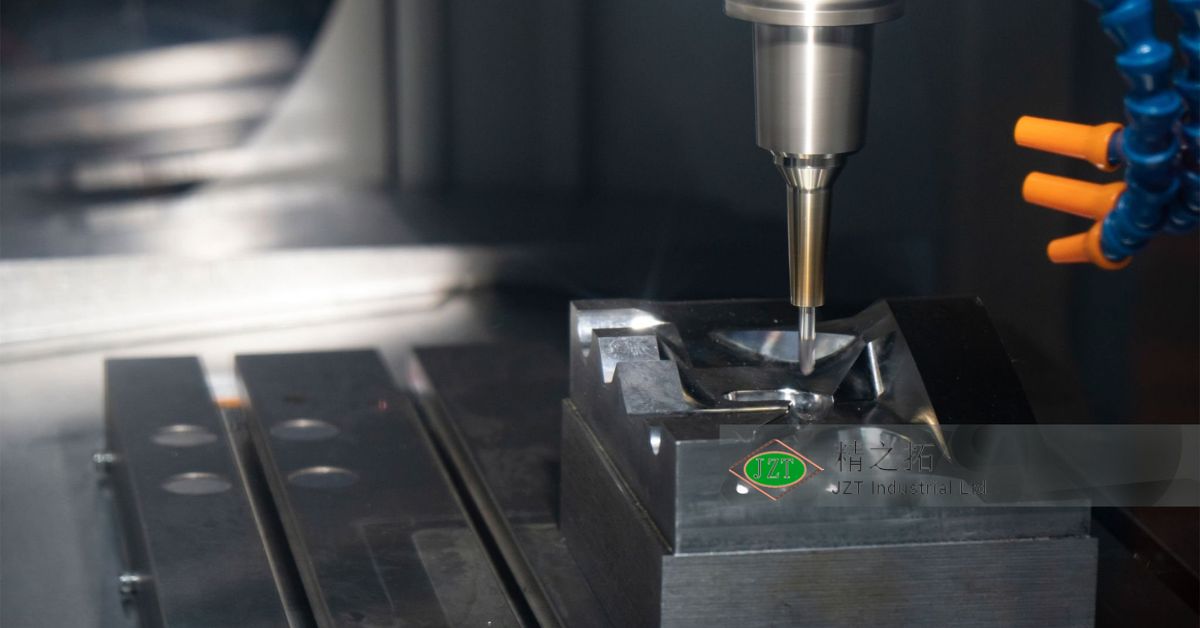
Tooling Fabrication
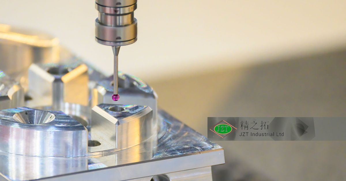
Before a single part is made, engineers must fabricate the mold itself using advanced machining centers. This stage involves cutting the core (B-side) and cavity (A-side) from metal blocks to match your exact CAD specifications.
- CNC Milling: Removes the bulk of the metal material.
- EDM (Electrical Discharge Machining): burns complex shapes into the steel using electrodes.
- Polishing: Smooths the surface to the required finish standard.
Now that you understand how the tool is built, let’s look at how it runs.
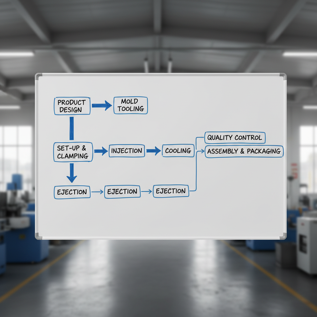
The Production Cycle
The production cycle is a finely tuned sequence of events designed to maximize speed and consistency. You can visualize this as a four-step loop that runs continuously.
- Clamping: The mold halves are pressed together.
- Injection: Molten plastic fills the cavity.
- Cooling: The part solidifies (often the longest step).
- Ejection: Pins push the part out of the mold.
Key Takeaway
Understanding the cycle allows you to design parts that cool evenly and eject cleanly. Minimizing the cooling phase is the most effective way to reduce part cost.
| Step | Action | Critical Factor | |
|---|---|---|---|
| 1 | Serrage | Tonnage force | |
| 2 | Injection | Fill speed/Pressure | |
| 3 | Refroidissement | Wall thickness | |
| 4 | Éjection | Angles de dépouille |
Optimizing the cooling phase through uniform design is your biggest lever for cost reduction.
What Types of Plastic Injecting Mould Methods Exist?
While the standard process involves a single material, several specialized variations exist to meet complex product requirements. A specialized plastic injecting mould may be required if your part needs rubberized grips, metal threads, or high-performance silicone properties.
Choosing the right method early in the design phase is critical for determining your tooling budget. Standard thermoplastic molding is the most common, but advanced applications often require multi-material capabilities.
Thermoplastic vs. LSR
Most consumer products use thermoplastic resins, which melt when heated and re-harden when cooled. In contrast, Liquid Silicone Rubber (LSR) uses a thermoset process where a chemical reaction cures the material permanently.
- Thermoplastiques : Re-meltable, recyclable, vast material options.
- LSR: Heat resistant, biocompatible, flexible, permanent cure.
With the basic material types defined, let’s consider combining them.
Overmolding and Insert Molding
These techniques allow you to integrate multiple materials or components into a single molded part. This reduces assembly time and improves the structural bond between materials.
- Overmolding: Molding a soft rubber (TPE) over a hard plastic substrate.
- Insert Molding: Placing a metal screw or bushing into the mold before injection.
Key Takeaway
Advanced molding methods increase tooling complexity but significantly reduce downstream assembly costs. They allow you to create premium-feeling products with integrated functionality.
| Method | Best For | Primary Benefit | |
|---|---|---|---|
| Thermoplastic | General parts | Cost & Variety | |
| LSR | Medical/Seals | Résistance à la chaleur | |
| Surmoulage | Grips/Handles | Ergonomics | |
| Moulage par insertion | Électronique | Integrated Metal |
Select overmolding or insert molding when your design requires multi-material properties that assembly adhesives cannot reliably achieve.
Why Choose a Plastic Injecting Mould for Production?

Injection molding is the industry standard for mass production because it offers the lowest price per part once the volume threshold is met. Although the initial investment in a plastic injecting mould is significant, the ability to produce millions of identical parts amortizes this cost rapidly.
Unlike 3D printing, which has a flat cost curve, injection molding becomes exponentially cheaper as quantities increase. This makes it the only viable choice for scalable commercial products in automotive, medical, and consumer sectors.
Cost vs. Volume Analysis
You must weigh the high upfront tooling cost against the low variable unit cost. For low volumes (under 100 units), machining or printing is often cheaper.
- 3D Printing: 0tooling,20/part.
- Injection Molding: 10,000tooling,1/part.
The crossover point usually occurs between 500 and 1,000 units.
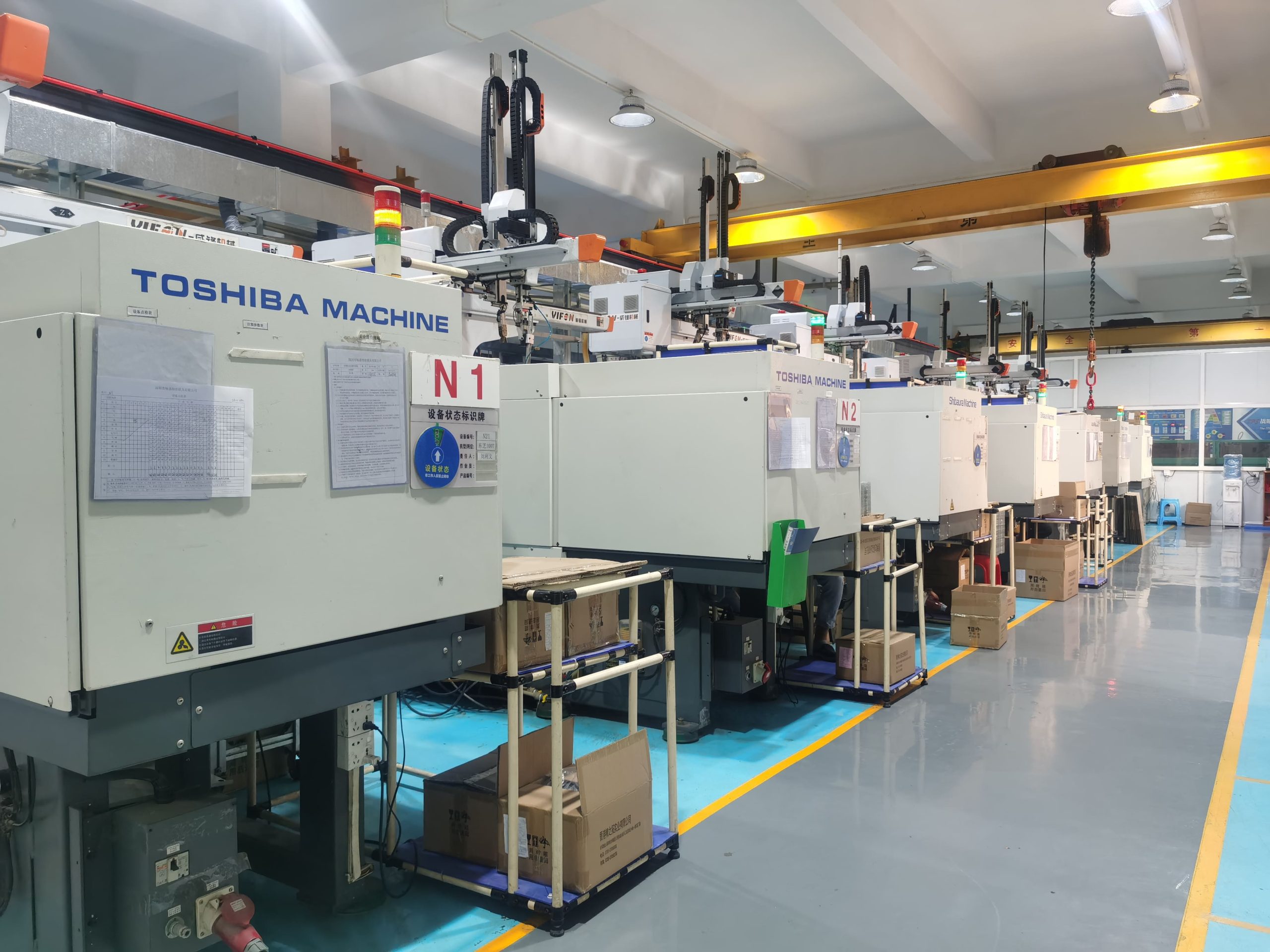
Efficiency in Manufacturing
Efficiency is driven by cycle time; the faster the mold opens and closes, the cheaper the part. Implementing strategies for reducing molding cycle times can save thousands of dollars over a production run.
- Multi-cavity molds: Make 4, 8, or 16 parts at once.
- Automation: Robots remove parts instantly.
Key Takeaway
Injection molding is an investment in scalability that pays off through speed and consistency. Your initial capital expenditure secures a reliable supply chain for years.
| Factor | 3D Printing | Moulage par injection | |
|---|---|---|---|
| Setup Cost | Low | High | |
| Unit Cost | High | Low | |
| Speed | Slow | Fast | |
| Material | Limited | Extensive |
Conduct a break-even analysis to determine the exact production volume where molding becomes more profitable than prototyping methods.
How Critical is Wall Thickness in a Plastic Injecting Mould?
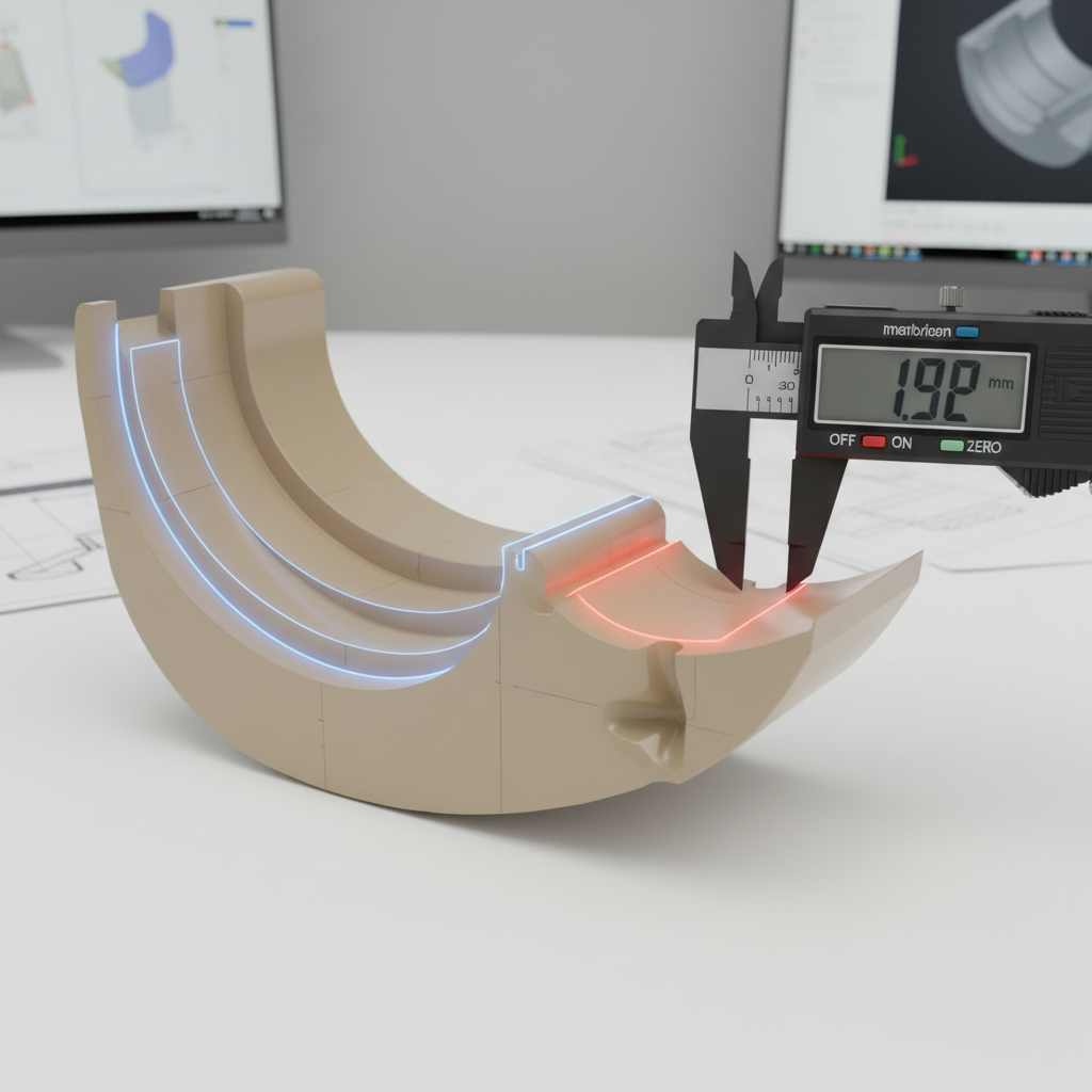
Wall thickness is arguably the single most important factor in ensuring a defect-free molded part. A well-engineered plastic injecting mould relies on uniform walls to ensure the molten plastic flows smoothly and cools at an even rate throughout the geometry.
If walls are inconsistent, thick sections will cool slower than thin sections, causing internal stresses. This leads to unsightly sink marks, structural warping, and potential part failure.
Managing Uniformity
You should aim to keep the wall thickness constant across the entire part. If a transition is necessary, it should be gradual rather than abrupt to prevent flow turbulence.
- Standard Range: 2mm to 4mm is ideal for most plastics.
- Transition Rule: Ramp thickness changes over a distance of 3x the wall thickness.
Let’s see how to handle thick features without adding mass.
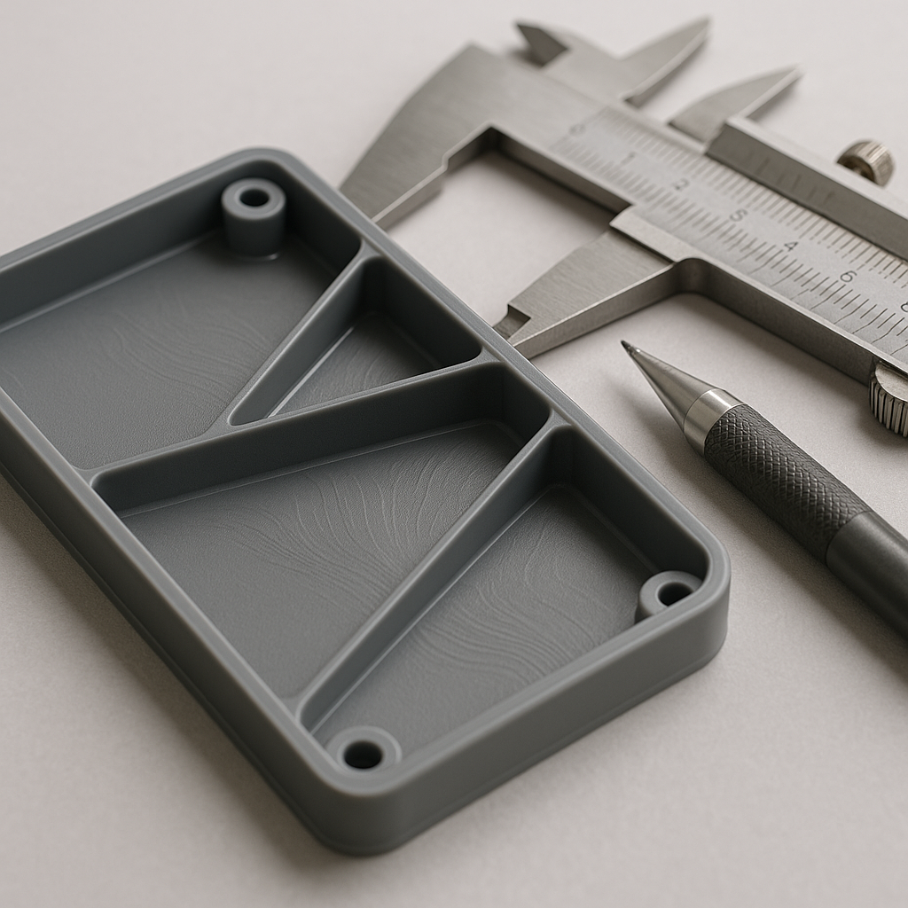
Core Geometry
To maintain uniformity in bulky areas, you must “core out” the material. This involves removing the interior mass and leaving only structural ribs to support the shape.
- Ribs: Add strength without bulk.
- Bosses: Use gussets to support screw columns instead of thick walls.
Key Takeaway
Adhering to strict wall thickness guidelines prevents the vast majority of cosmetic and structural defects. It forces you to design efficient, lightweight parts that cool quickly.
| Feature | Consequence of Poor Design | Solution | |
|---|---|---|---|
| Thick Wall | Traces d'affaissement | Core out material | |
| Thin Wall | Short Shots (incomplete fill) | Increase thickness | |
| Uneven Wall | Gauchissement | Gradual transitions |
Always review your CAD model using thickness analysis tools to identify and core out heavy sections before tooling begins.
Do Undercuts Complicate a Plastic Injecting Mould Design?
Undercuts are features that prevent the mold from opening or the part from ejecting because they are physically trapped by the metal tool. When designing for a plastic injecting mould, you must identify these interlocks early, as they require complex and expensive mechanisms to release.
Simple molds open in a straight line (A-side and B-side separating). Any feature like a side hole, snap fit, or recessed groove that is not parallel to this opening direction is considered an undercut.
Side Actions and Cams
To resolve undercuts, mold makers use side-actions or cams. These are moving pieces of metal that slide into place before injection and pull away sideways before the mold opens.
- Pros: Allows for complex geometry like side ports.
- Cons: Increases tooling cost and maintenance.
If cams are too expensive, simple design tweaks can help.
Angles de dépouille
Draft is a slight taper added to vertical walls to ensure they release from the mold without dragging. Without draft, the vacuum pressure and friction would cause the part to stick and tear.
- Minimum Draft: 0.5 degrees for vertical walls.
- Texture Draft: 1.5 degrees per 0.001″ of texture depth.
Key Takeaway
While undercuts enable complex features, they significantly drive up the cost of the mold. Draft angles are a non-negotiable requirement for successful ejection.
| Feature | Cost Impact | Complexity | |
|---|---|---|---|
| Straight Pull | Low | Low | |
| Sliding Shutoff | Medium | Medium | |
| Side Action (Cam) | High | High | |
| Pickout Insert | Medium | High (Manual labor) |
Eliminate undercuts where possible by redesigning the part, or budget for side-actions if the feature is critical to function.
What Are the Gate Options for a Plastic Injecting Mould?
The gate is the precise entry point where molten plastic leaves the runner system and enters the part cavity. The location and type of gate on your plastic injecting mould will determine the flow pattern, structural strength of ribs, and the visibility of the “vestige” scar left behind.
Choosing the wrong gate location can result in “knit lines”—weak points where two flow fronts meet—or cosmetic blemishes on visible surfaces. You must balance aesthetic needs with the physics of plastic flow.
Common Gate Types
Different gates serve different purposes depending on the part’s geometry and cosmetic requirements.
- Edge/Tab Gate: Common, simple, leaves a scar on the side edge.
- Sub/Tunnel Gate: Shears off automatically below the parting line; great for automation.
- Hot Tip: Direct injection on the top surface; ideal for round parts but leaves a small dimple.
Once the plastic is in, it eventually needs to come out.
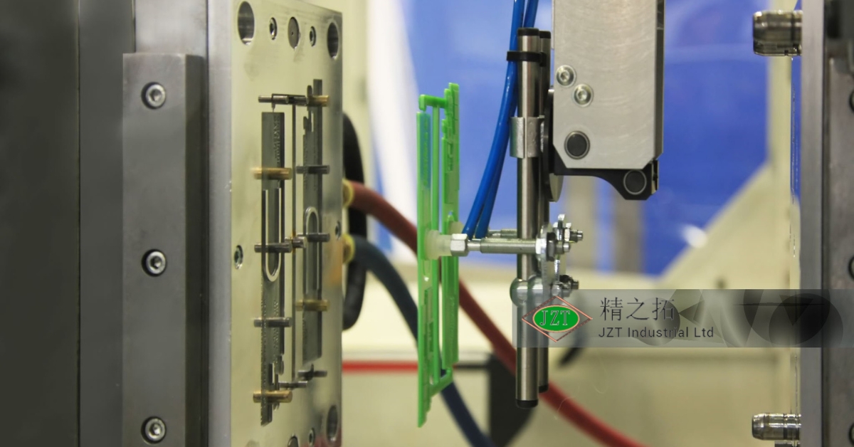
Ejector Pin Placement
Ejector pins physically push the part off the B-side of the mold. You must place them on structural areas (like ribs or bosses) to avoid punching through the part.
- Witness Marks: Pins leave small circles on the part surface.
- Placement: Always locate pins on the non-cosmetic side of the part.
Key Takeaway
Gate and ejector placement are critical for both the cosmetic appearance and the physical integrity of the part. Proper planning hides unsightly marks and ensures robust filling.
| Gate Type | Vestige Location | Auto-Trim? | |
|---|---|---|---|
| Tab Gate | Part Edge | No | |
| Tunnel Gate | Part Side/Bottom | Yes | |
| Hot Tip | Part Top Surface | Yes | |
| Cashew Gate | Hidden/Rear | Yes |
Specify “cosmetic surfaces” clearly in your drawings so the mold engineer places gates and pins in non-critical areas.
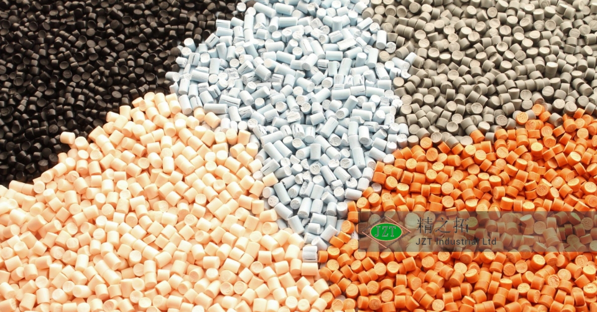
Which Material Is Best for Your Plastic Injecting Mould?
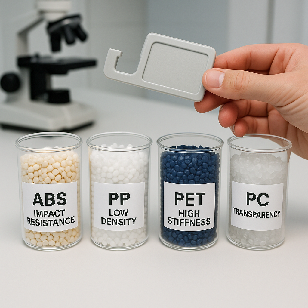
Selecting the right resin is a balance between mechanical performance, environmental resistance, and cost. The design of your plastic injecting mould must account for the specific shrink rate of the chosen material, meaning you often cannot switch resins easily once the tool is cut.
Thousands of thermoplastic options exist, but they generally fall into commodity or engineering grades. Your choice dictates the durability and application of the final product.
Engineering vs. Commodity Resins
Commodity plastics are cheap and versatile, while engineering resins offer high performance.
- Commodity: PP (Polypropylene), PE (Polyethylene), PS (Polystyrene).
- Engineering: ABS (LEGO plastic), PC (Polycarbonate), Nylon (Polyamide).
For specialized applications, additives can change everything.
Additives and Strengtheners
You can enhance base resins with additives to meet specific needs, such as material safety and durability in consumer goods.
- Glass Fiber: dramatically increases strength but reduces flexibility.
- UV Stabilizers: prevent yellowing and cracking in sunlight.
- Flame Retardants: essential for electronics and automotive parts.
Key Takeaway
Material selection defines the lifespan and utility of your product. It is a decision that must be finalized before mold manufacturing begins due to shrinkage rates.
| Material | Key Property | Typical Use | |
|---|---|---|---|
| ABS | Impact Strength | Électronique grand public | |
| PC | Clarity & Toughness | Lenses/Housings | |
| PP | Résistance chimique | Food Containers | |
| Nylon | Wear Resistance | Gears/Bearings |
Consult a material data sheet (MDS) to verify that your chosen resin meets all environmental and mechanical stress requirements.
How Do Surface Finishes Affect a Plastic Injecting Mould?
Surface finish is not just about aesthetics; it affects how the part releases from the tool and how it feels to the user. A plastic injecting mould can be polished to a mirror shine or chemically etched to create deep leather-like textures.
The Society of the Plastics Industry (SPI) has standardized these finishes. Choosing a higher grade finish generally increases tooling costs due to the extra manual labor required to polish the steel.
Standard Finish Options
Finishes are categorized by the method used to achieve them.
- Grade A (Diamond Buff): High gloss, mirror finish. Requires high-grade steel.
- Grade B (Grit Paper): Smooth, semi-gloss. Removes machining marks.
- Grade C (Stone): Matte finish. Good for hiding fingerprints.
Texture offers a functional alternative to polishing.
Mold Tech Textures
Texturing involves etching a pattern directly into the mold steel.
- Function: improves grip and hides sink marks.
- Draft Requirement: You must add extra draft (1.5 degrees per 0.001″ depth) so the texture doesn’t scrape off during ejection.
Key Takeaway
Surface finishes add perceived value and functionality to your part. However, aggressive textures require increased draft angles to prevent drag marks during ejection.
| SPI Grade | Description | Typical Application | |
|---|---|---|---|
| A-1 | High Polish | Lenses, Mirrors | |
| B-1 | Medium Polish | Cosmetic Cases | |
| C-1 | Stone Finish | Structural Parts | |
| D-1 | Bead Blast | Handles, Grips |
Specify the lowest acceptable finish for non-cosmetic parts to save on tooling costs, and reserve high-polish for visible surfaces.
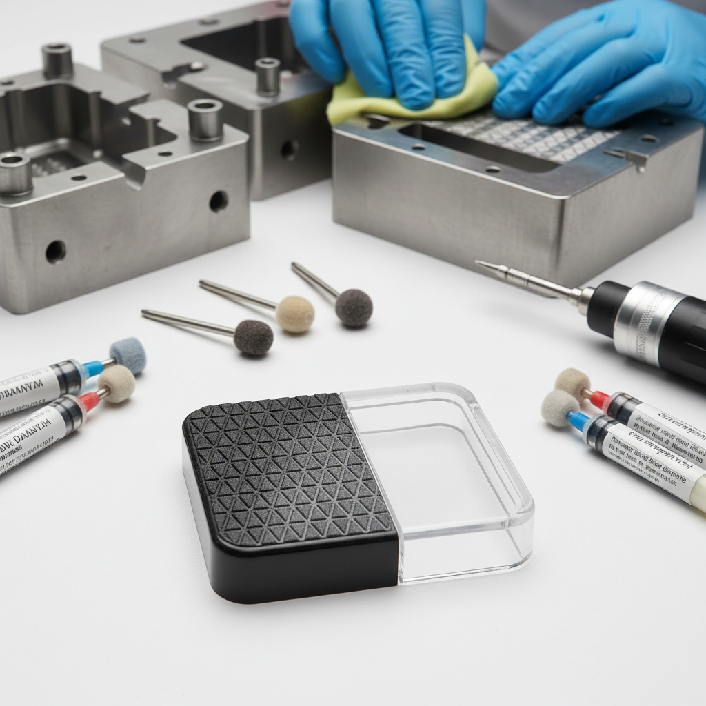
Can You Modify Parts After the Plastic Injecting Mould?
Sometimes, the geometry you need is impossible to mold directly, or you require assembly features that molding cannot provide. While the plastic injecting mould delivers the primary shape, post-processing techniques allow you to modify, assemble, and finish the part to meet complex specifications.
These secondary operations bridge the gap between a raw molded component and a market-ready product. They are often used to address limitations or add value through branding.
Advanced Molding Techniques
Some modifications happen during the molding cycle using manual inserts.
- Pickouts: Loose pieces of metal placed in the mold by hand to create an undercut, then removed from the part after ejection.
- Threaded Inserts: Brass nuts pressed into the plastic (heat staking) after molding to provide durable threads.
Part Marking and Assembly
Once the part is ejected, further customization is possible.
- Ultrasonic Welding: Uses high-frequency vibrations to fuse two plastic parts together without glue.
- Pad Printing: Transfers 2D ink logos onto 3D surfaces.
Key Takeaway
Post-molding modifications expand your design possibilities beyond the limits of the steel tool. They enable complex assemblies and high-quality branding that a raw mold cannot achieve.
| Process | Purpose | Timing | |
|---|---|---|---|
| Pickout | Create Undercut | During Molding | |
| Heat Staking | Add Threads | Post-Molding | |
| Ultrasonic Weld | Join Parts | Post-Molding | |
| Pad Print | Branding | Post-Molding |
Plan for secondary operations in your budget if your design requires complex undercuts or permanent branding.
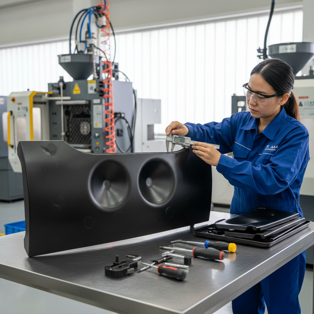
What Quality Standards Govern a Plastic Injecting Mould?

In manufacturing, consistency is king. A high-quality plastic injecting mould provider adheres to rigorous international standards to ensure that the millionth part matches the first part exactly. Without these systems, variations in process parameters can lead to rejected batches and wasted time.
Top-tier manufacturers use data-driven approaches to validate the mold before full-scale production begins. This scientific approach removes the guesswork from tuning the machine.
Validation Processes
Validation ensures the tool works as designed.
- Scientific Molding: A process of decoupling filling, packing, and holding phases to find the perfect stable process window.
- First Article Inspection (FAI): A comprehensive report measuring every dimension of the first sample parts against the drawing tolerances.
Industry Certifications
Certifications indicate a supplier’s capability to manage risk and quality.
- ISO 9001: General quality management.
- ISO 13485: Required for medical device manufacturing.
- IATF 16949: Strict standard for the automotive supply chain.
Key Takeaway
Quality certifications and scientific molding processes are your insurance policy against production failures. They guarantee that your supplier has the discipline to maintain tight tolerances over time.
| Standard | Focus | Industry | |
|---|---|---|---|
| ISO 9001 | Process Management | General | |
| ISO 13485 | Risk Management | Médical | |
| FAI | Dimensional Accuracy | All | |
| PPAP | Process Stability | Automobile |
Always request a First Article Inspection report to verify that the physical parts match your digital CAD file dimensions.
Conclusion
Navigating the transition from digital design to physical production is complex, but the rewards of injection molding are unmatched. By understanding the mechanics of the plastic injecting mould—from the importance of uniform wall thickness to the strategic selection of resins—you can design parts that are not only manufacturable but also cost-effective. Avoiding common pitfalls like undercuts and poor draft angles early in the design phase will save you thousands of dollars and weeks of delay.
Your success depends on partnering with a manufacturer who understands these intricacies. Whether you are sourcing mold manufacturing for a global automotive rollout or a niche medical device, the principles of good design remain the same.
Ready to transform your concept into reality? Contact us today to speak with our engineering team. We are committed to delivering innovative molding solutions that bridge the gap between your vision and a market-ready product.
Questions fréquemment posées (FAQ)
Can I use 3D printed molds for injection molding?Yes, but they are only suitable for extremely low volumes (10-50 parts). 3D printed molds degrade rapidly under heat and pressure, making them useful only for functional fit checks, not production.
What’s the best way to reduce the cost of my mold?Simplify your design to eliminate undercuts and side-actions. By designing a “straight-pull” part that requires no moving mold mechanisms, you can reduce tooling costs by 30% or more.
How do I know if my part design is ready for molding?You should run a DFM (Design for Manufacturing) analysis. Most professional molders provide a DFM report that highlights issues like insufficient draft, thick walls, or impossible geometries before they cut steel.
What is the difference between a cold runner and a hot runner?A cold runner solidifies with the part and must be trimmed (waste), while a hot runner keeps the plastic molten inside the tool. Hot runners reduce waste and cycle time but are significantly more expensive to build.
Can I change the mold design after it has been made?It is easy to remove metal (“metal-safe” changes) to add plastic to the part, but very difficult to add metal back to the tool. Always start with smaller dimensions if you are unsure, as you can cut more steel later to increase size.